H-Bridge motor driver
Want to drive large inductive loads? You've come to the right place.
This design was done as an experiment to convert large DC motors to a servo motor using an analog feedback. It can be programmed to do pretty much anything depending the requirement.
In the current configuration, the outputs can handle 100A sustained. Additional flyback diodes and LC filters are used to protect power electronic from inductive kickback.
Specifications
- Number of channels: 2
- Voltage input max: 48V
- Current output max: 100A
- Output filter: LC
- Analog inputs: 2
- Digital inputs (isolated): 2
- Digital outputs: 2
- Control method: PID
This PCB was designed using EasyEDA for couple of reasons. You can get all the PCBs assembles in china for a very reasonable price through its parent company JLCPCB no matter what your quantity is. It's a great way to get professionally assembled PCBs for a one off job like this without going trough the hassle of sourcing parts and hand soldering them.
Schematic
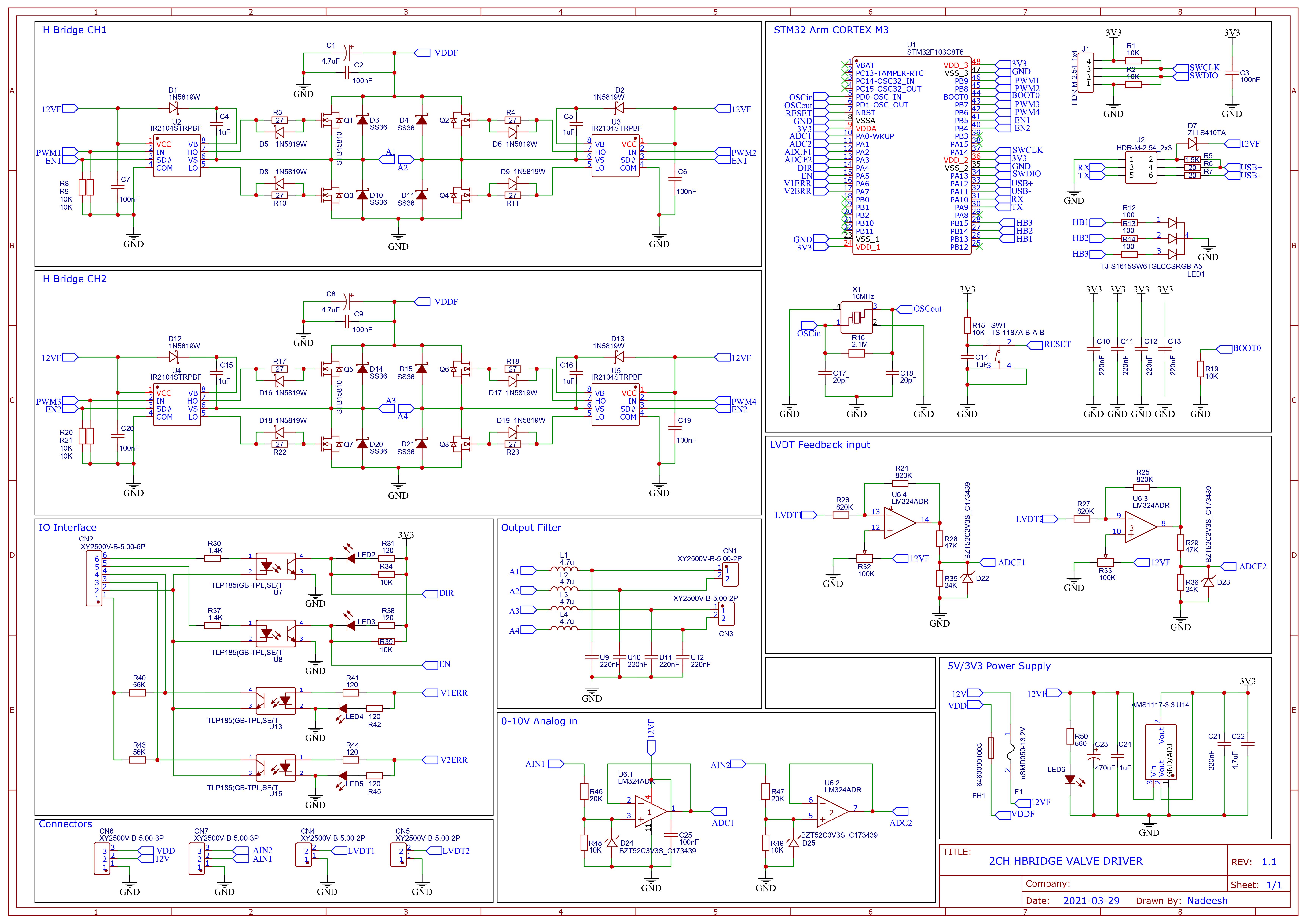
Power section of this circuit is a straight copy of the application circuit given in the datasheet for the IR2104 mosfet gate driver. All four fets in the circuit are N-type and the two high sides switches are driven using a technique called bootstrapping using the aforementioned IR2104 gate driver.
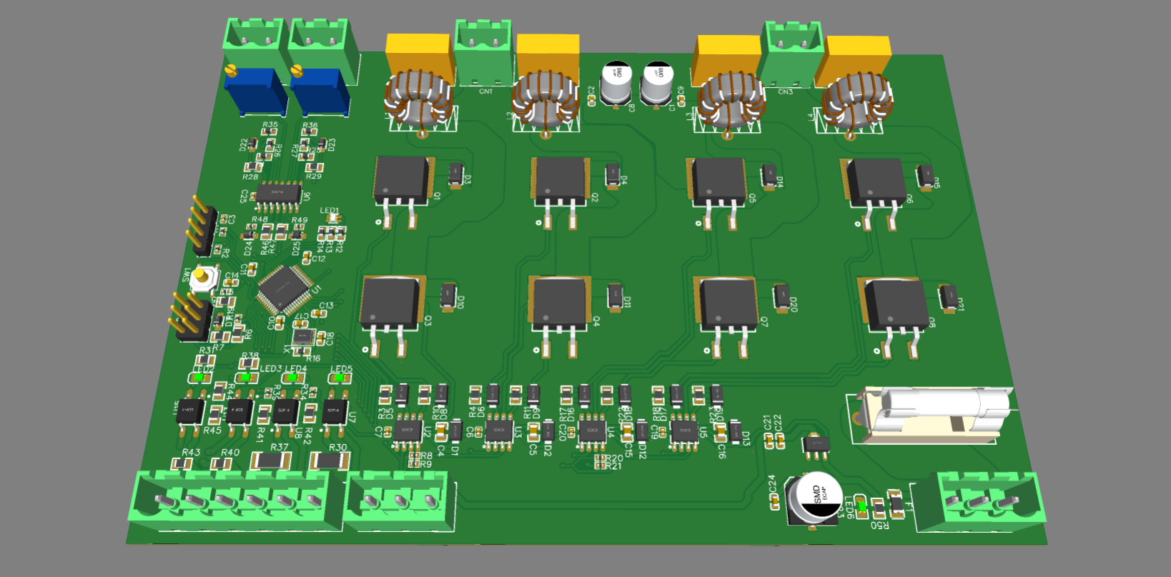
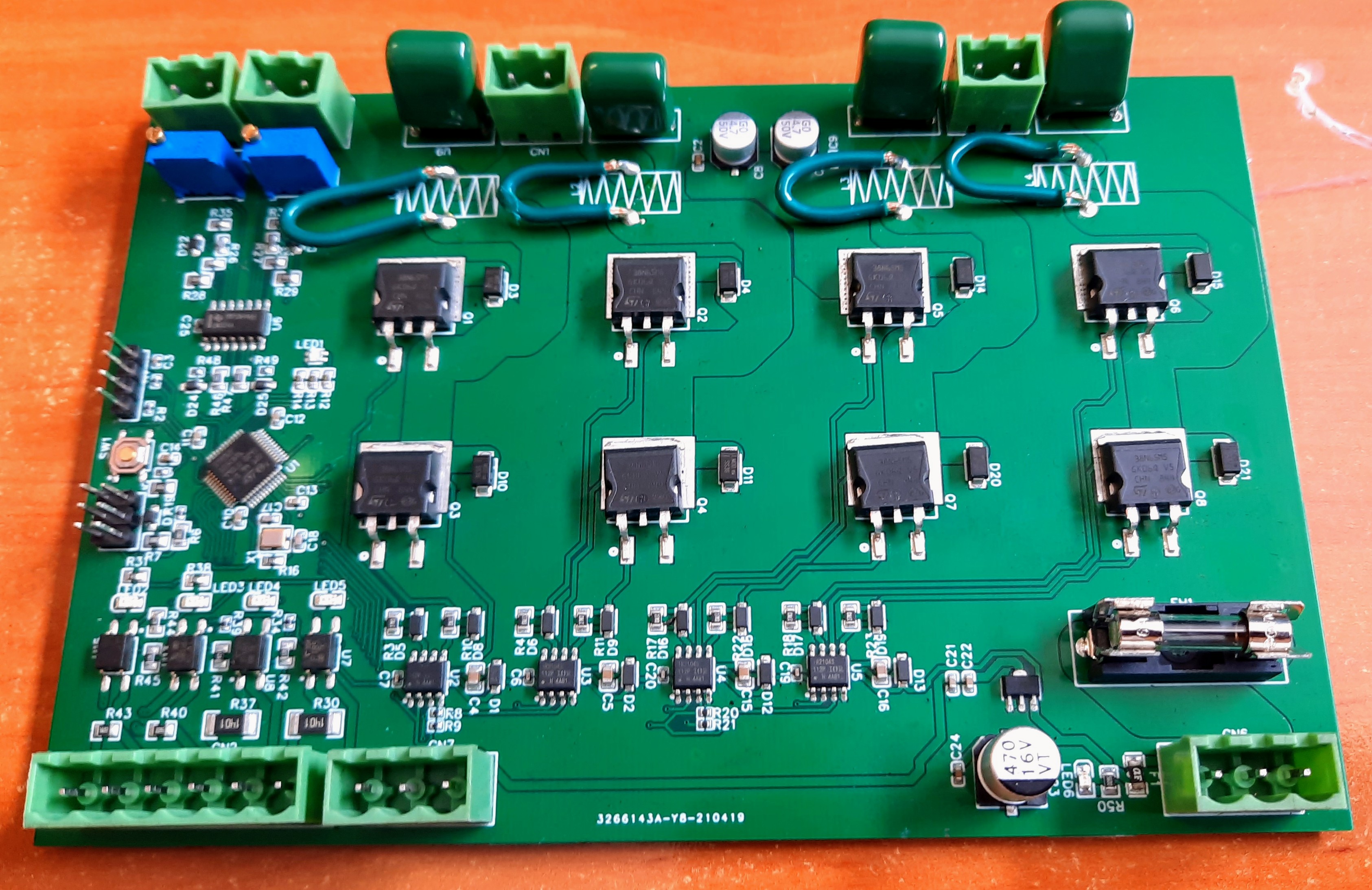
Assembled PCB
Testing
Here's little clip of testing the board with a real world application. The 24V DC motor was connected to the output channel 1 of the H-Bridge and the output shaft of the motor was attached to a 10 turn potentiometer to act as an analog feedback. This gives us the ability to control the shaft position of the motor in a closed loop control loop. A PID was used as the control algorithm and the video shows you the working system with minimal PID tuning.
You can find all the design files including the BOM and gerber files for manufacturing in my github
H-Bridge PCB github repo